
Singapore Polytechnic - Computer-Aided Design Keychain and Desk Organiser
Link to github: Github link
Introduction
‘Computer-Aided Design & Drafting’ aims to equip students with the knowledge of drawing office practice, ISO drawing standards and drawing skills using latest AutoCAD software and the ability to read and produce good technical sketches and projection drawings as a form of engineering communication. The module will cover basic 2D drawings, isometrics and orthogonal projections, 3D-Design using Autodesk software for 3D-Printing & Laser cutting assignments, and the use of workstation based CAD/CAM software for computer-aided drafting.
Assignment 1: Desk Organiser and Name Tag
As part of our Computer Aided Drafting module, we were tasked with the following:
-
Design a key chain
-
Design a desk organiser that fulfilled the following criteria:
- The key chain had to be integrated into the design
- Consist of at least 3 functions, e.g. pencil holder, stabler holder etc.
- Must not exceed 120mm x 120mm x 120mm
Key Chain
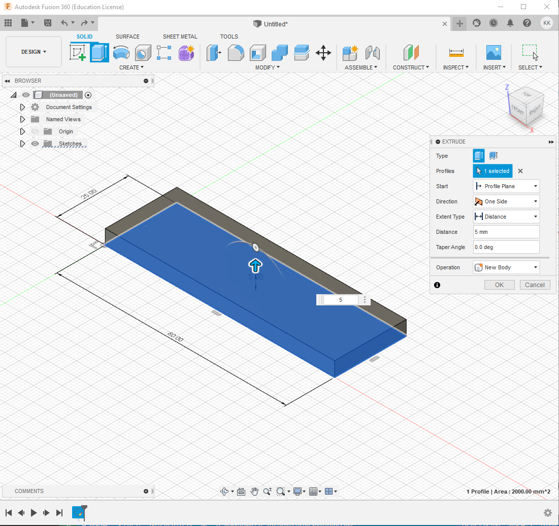
The design of the key chain is standardised throughout the course and as such was provided for us. We first had to draw an 80mm by 25mm base and extrude it by 5mm
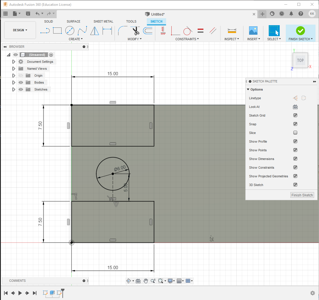
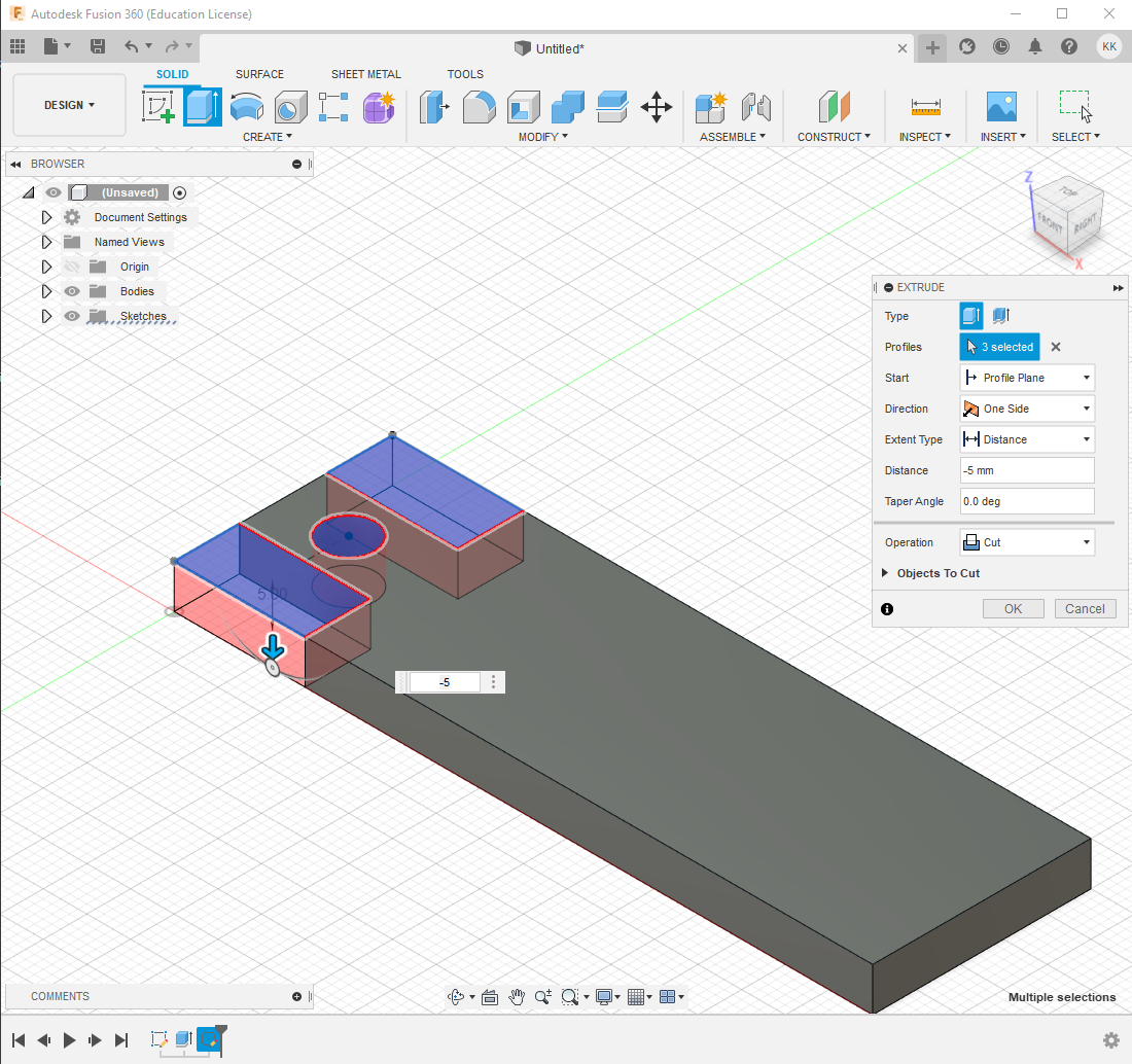
Second, to create the key ring, we drew 2 15mm by 7.5mm rectangles at the edge of the rectangle. A 6mm hole was also drawn between the 2 new rectangles. A construction line was use determine the exact location of were the circle should be placed. The extrude function was then used to cut out the rectangle and circle.
 |
| Designating area to cut |
 |
| Making the key ring |
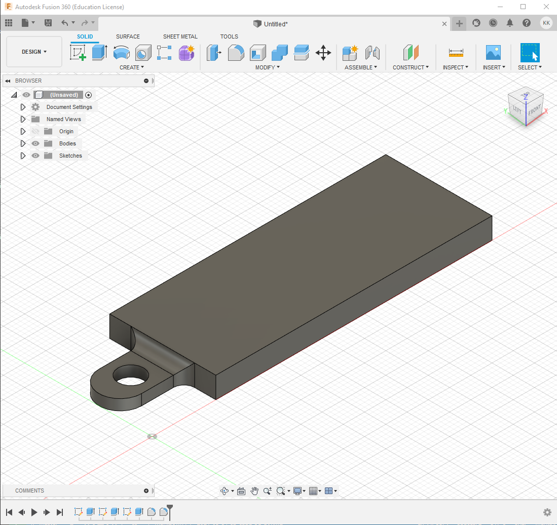
To further refine the design, we halved the height of the key ring, filleted and chamfer the edges accordingly.
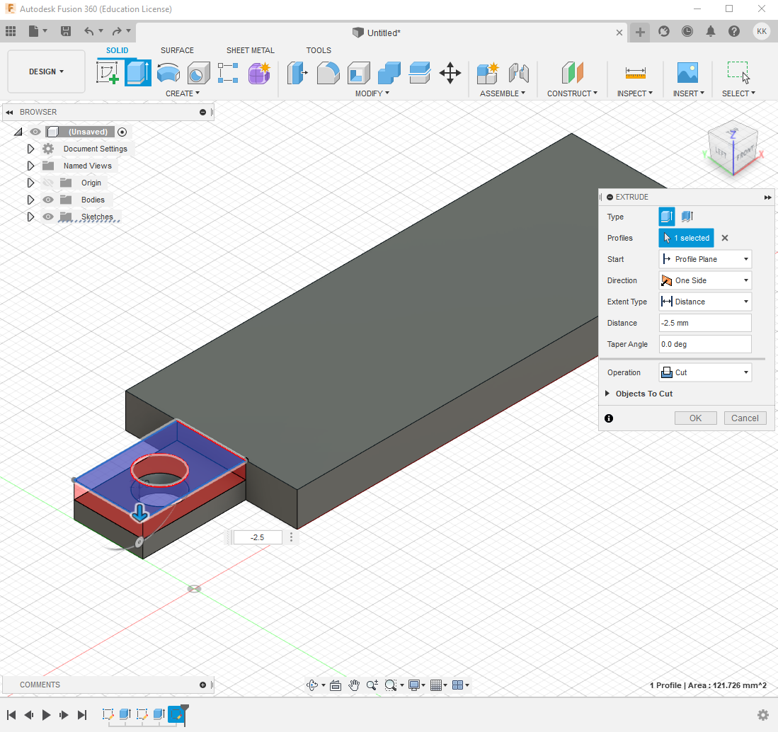 |
| Halving the height |
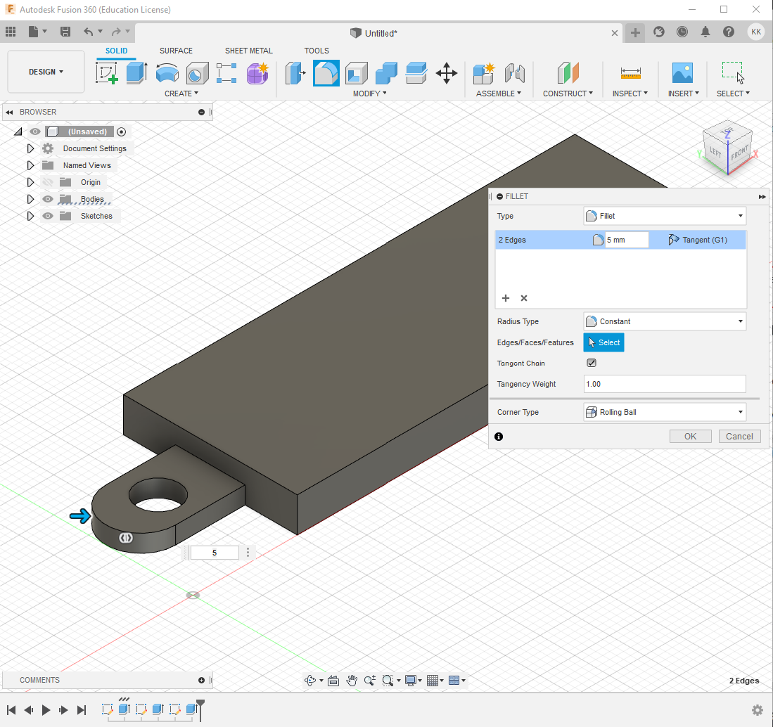 |
| Filleting edges of keyring by 5mm |
 |
| Filleting edge of the neck by 2.5mm |
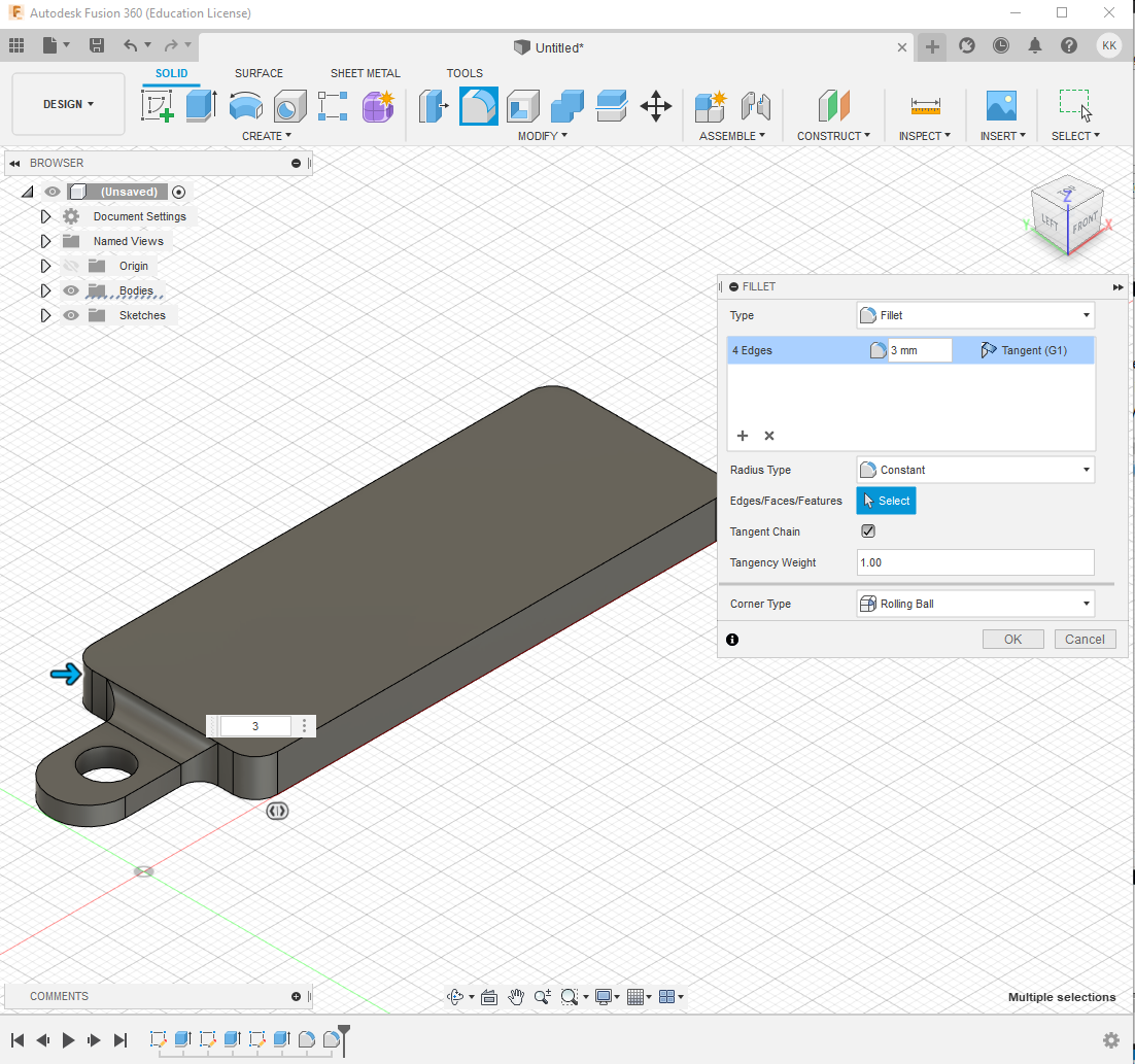 |
| Filleting edge of the keychain by 3mm |
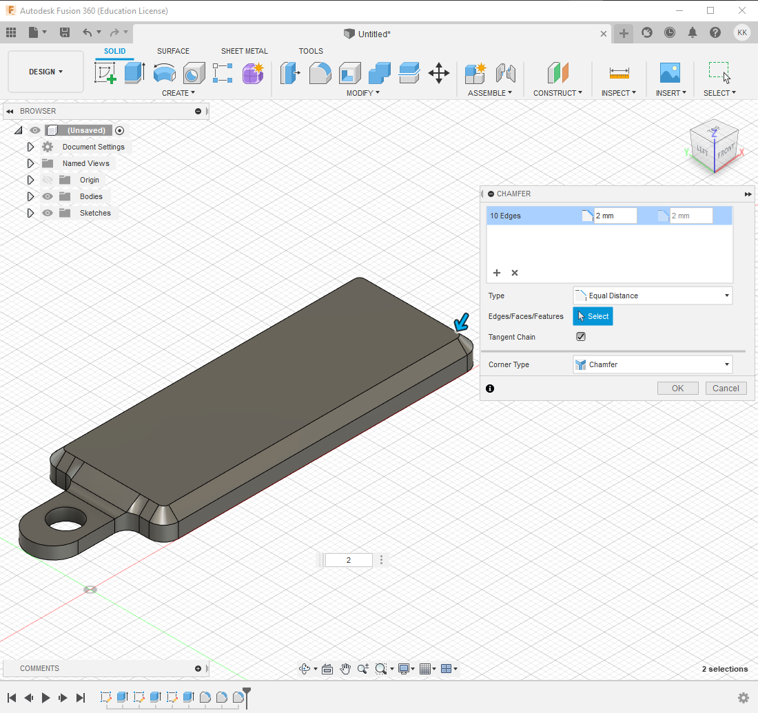 |
| Chamfering the top of the keychain by 2mm |
Lastly, we wrote our names on the keychain and extruded it to ‘stamp’ it onto the keychain.
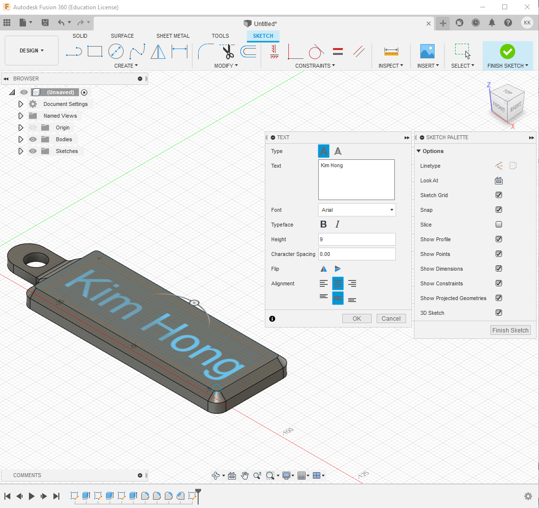 |
| Writing names on the keychain |
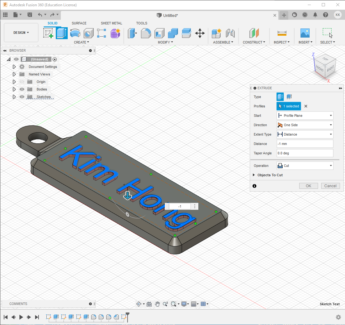 |
| Extruding our names |
And with that, we completed the keychain aspect of our assignment
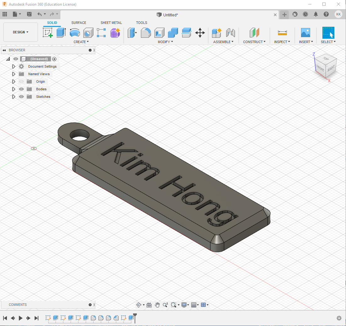 |
| The final product |
Desk Organiser
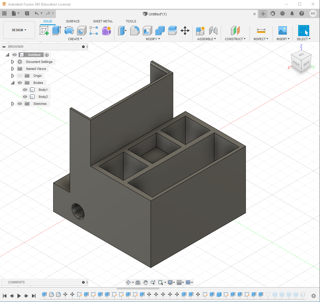
As per the stipulated requirements, my desk organiser has the following functions:
- Key chain integrated to the front of the design
- Phone holder at the front
- 4 silos for pens and similar objects
- 2 deep rectangular compartments for miscellaneous items
- 1 shallow rectangular compartment for erasers
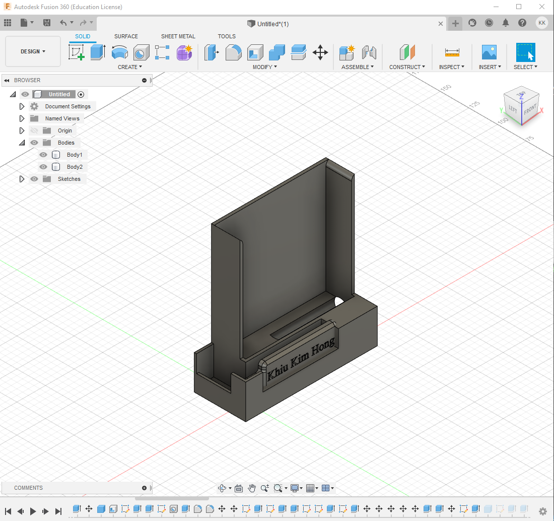
 |
| Front view |
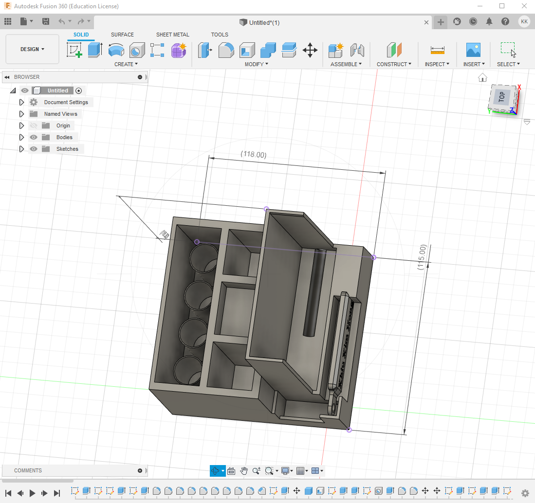 |
| Top view, a small compartment is present to accommodate keys |
Design thoughts and process: Phone compartment
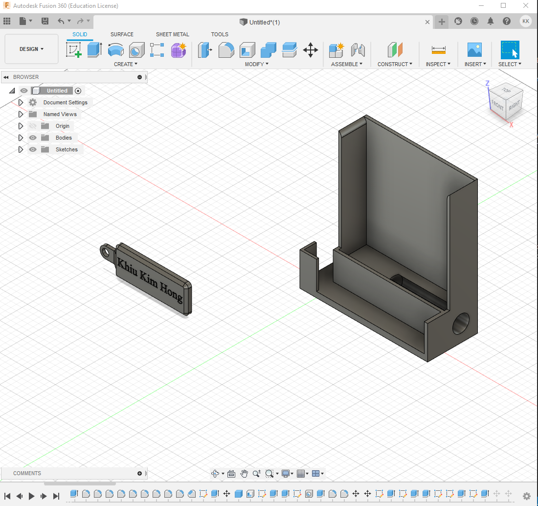
The key chain was first imported into a new file to allow easier visualisation for integration
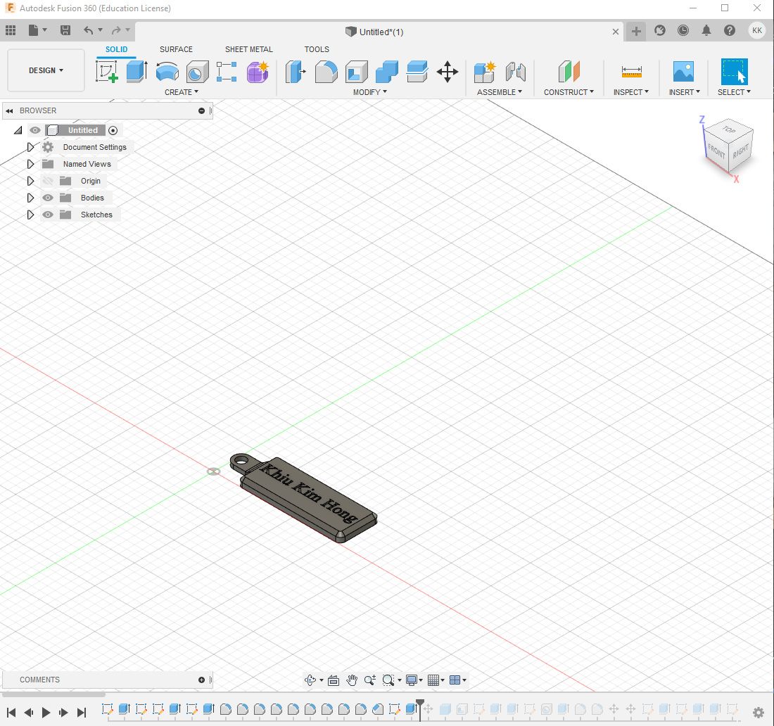 |
| Imported key chain |
The idea of the phone holder was an attempt by me to do something that I believe would be unique.
The structure of the phone holder was created using the create box command with the dimensions of 100mm by 30mm by 120mm
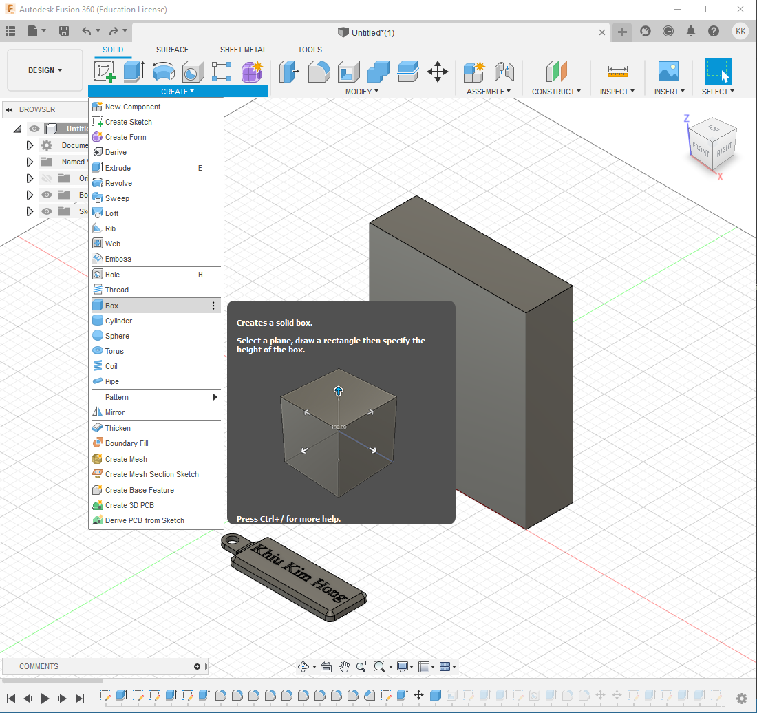 |
| Front view |
The structure was then extruded to make a platform to hold the phone. A hole was subsequently created with the hole command to allow for a charging cable to inserted into the phone holder. The edges were also filleted
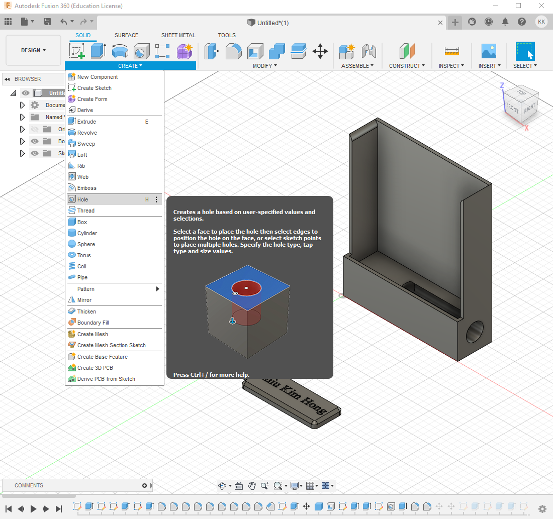 |
| Phone holder begins to take shape |
Design thoughts and process: Key chain integration
An ‘L’ shaped structure was created using sketch and extrude commands to allow for accommodation of the key chain. The idea behind the ‘L’ shape was to give a compartment for keys to be placed. This structure was then hollowed and trimmed.
The key chain was then moved into the compartment. The extrude commands was then used to ‘encase’ the key chain. The cut command was used to further refine the integration of the key chain with the desk organiser.Lastly, a segment of the structure was the extruded to make a compartment for the keys
Design thoughts and process: Stationary compartment
A new body at the back of the was created using the modify:press pull and modify:shell commands. The modify: press pull command was used again to raise the base of the middle structure of the 3 small rectangles.
The create:cylinder command along with the modify:shell command was used to create the cylinders meant to accommodate pens.
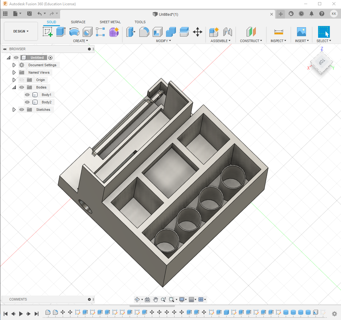
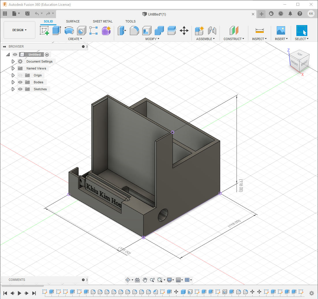
Lastly, dimension measurements were added as indicated in the submission requirements before being exported and submitted.
|
| Final design to be submitted |
Assignment 2: Phone Holder
In an interesting turn of events, assignment 2 requires us to design a smartphone holder using Fusion 360. Unlike assignment 1, where the designs were intended to be 3d printed, assignment 2 was intended to be laser cut instead. However due to COVID19, we only had to design and did not get to physically make the items.
According to the assignment, the smartphone holder must fit the following criteria:
- Must not exceed 150mm by 150mm by 150mm
- Must contain our names, class and student ID
- Must be made of at least 3 parts
With this I mind, I decided that my design will consist of the following
- A square shaped base to ensure stability
- A support structure that leans backwards to prevent the phone from falling over.
- A hole for a charging cable to pass through
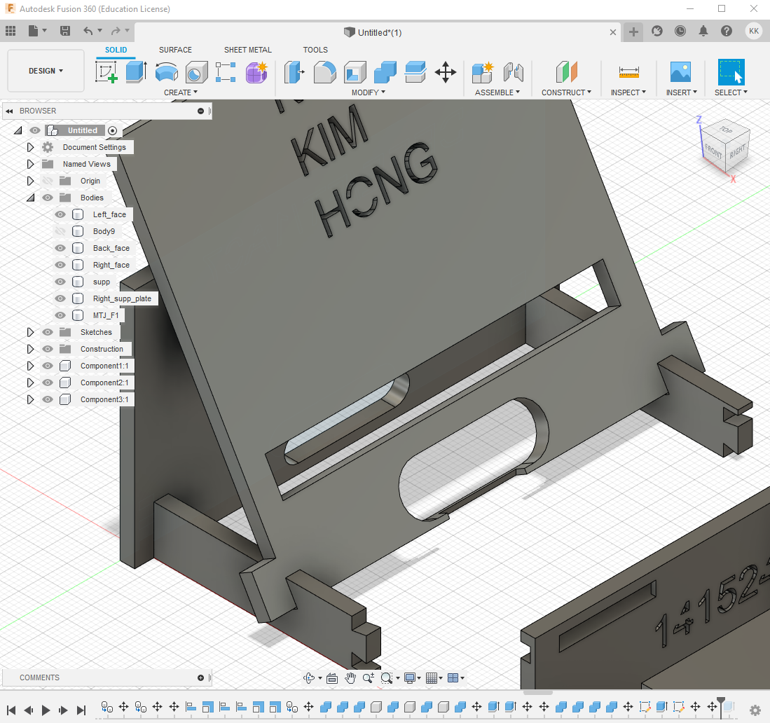
With this in mind, this was what the final product looks like:
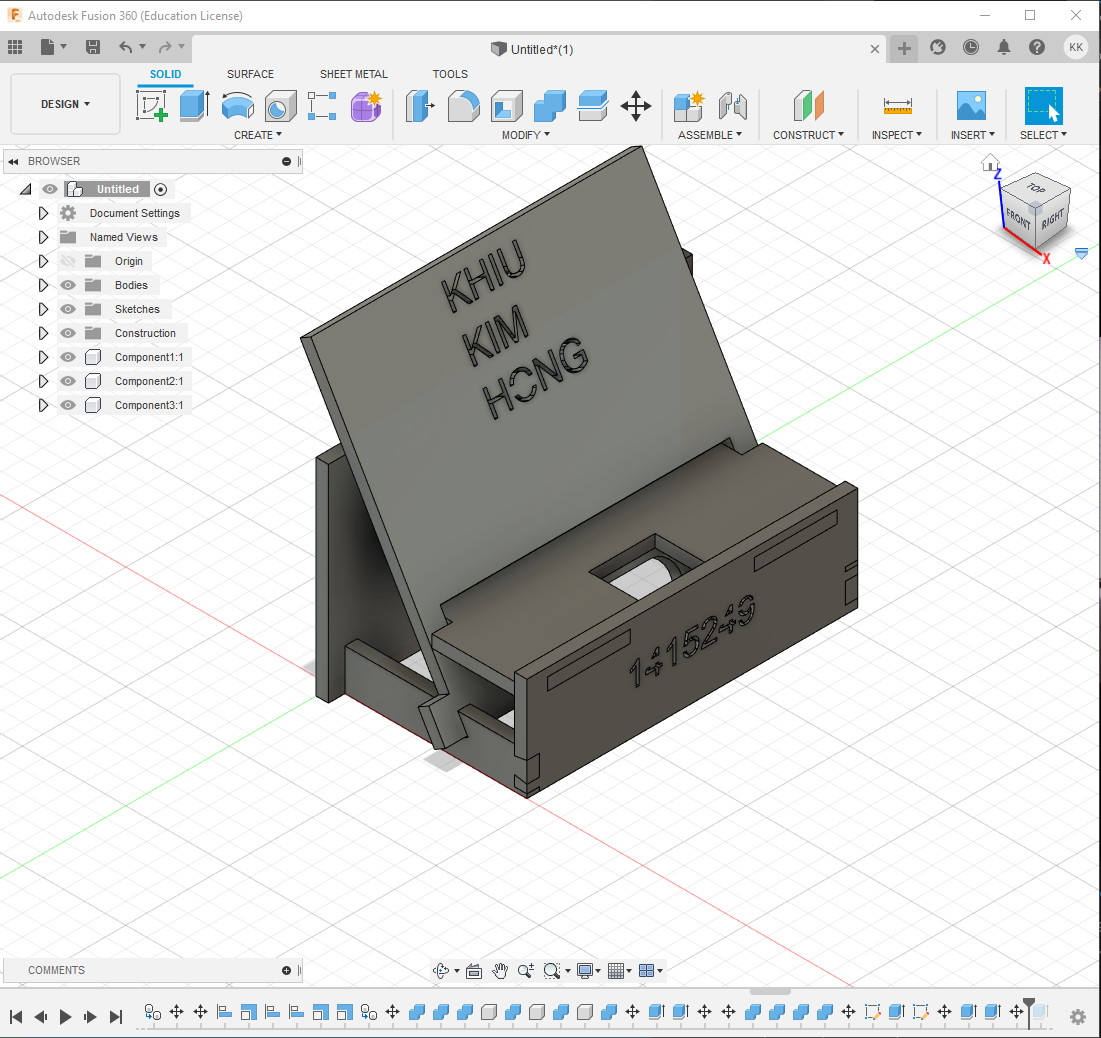 |
| Assembled model |
 |
| Intended laser cut layout |
General design notes
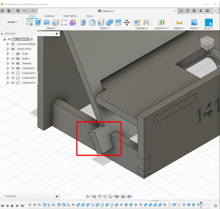
The entire structure was created using sketch and extrude commands. The holder uses mortise and tenon joints to allow for all component to be connected together. The exception are the front support joints, which uses dovetail joints for connection
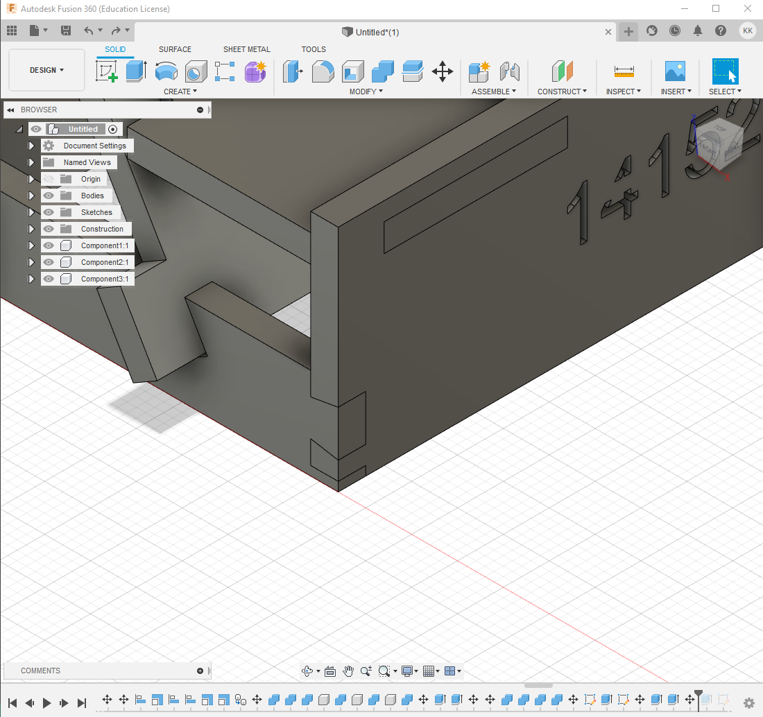 |
 |
| Dovetail joints in use |
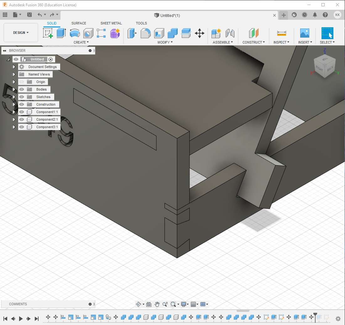
The modify:align command was used to stager the joints of the rear support while ensuring that they were equidistant from each other.
 |
| Rear staggered joints |
Joints were manually extruded The general assembly was done by manually moving the pieces into place and using the modify:combine:cut command to make the holes that the parts will be slotted in. The slots were then extruded slightly to allow for some leeway to during final assembly. Some of the joints were also extended for the same purpose.
 |
| parts extended to allow for better support |
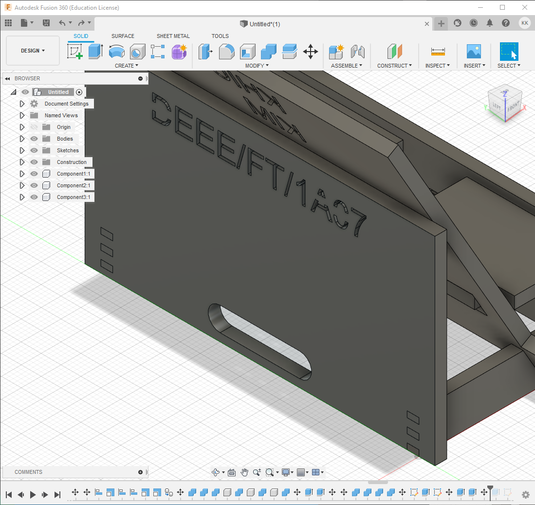
The command sketch:create:slot was used on the support structures to create holes that allows a charging cable to pass through.
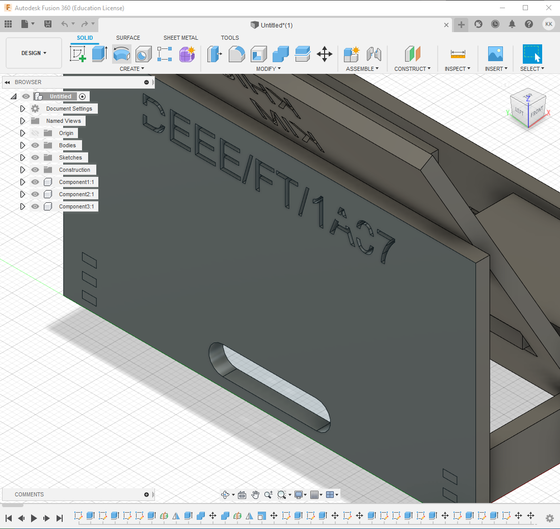 |
 |
| Slots for charging cables |
Laser cut layout
A copy of the assembled design file was saved. All parts were subsequently disassembled and laid flat.
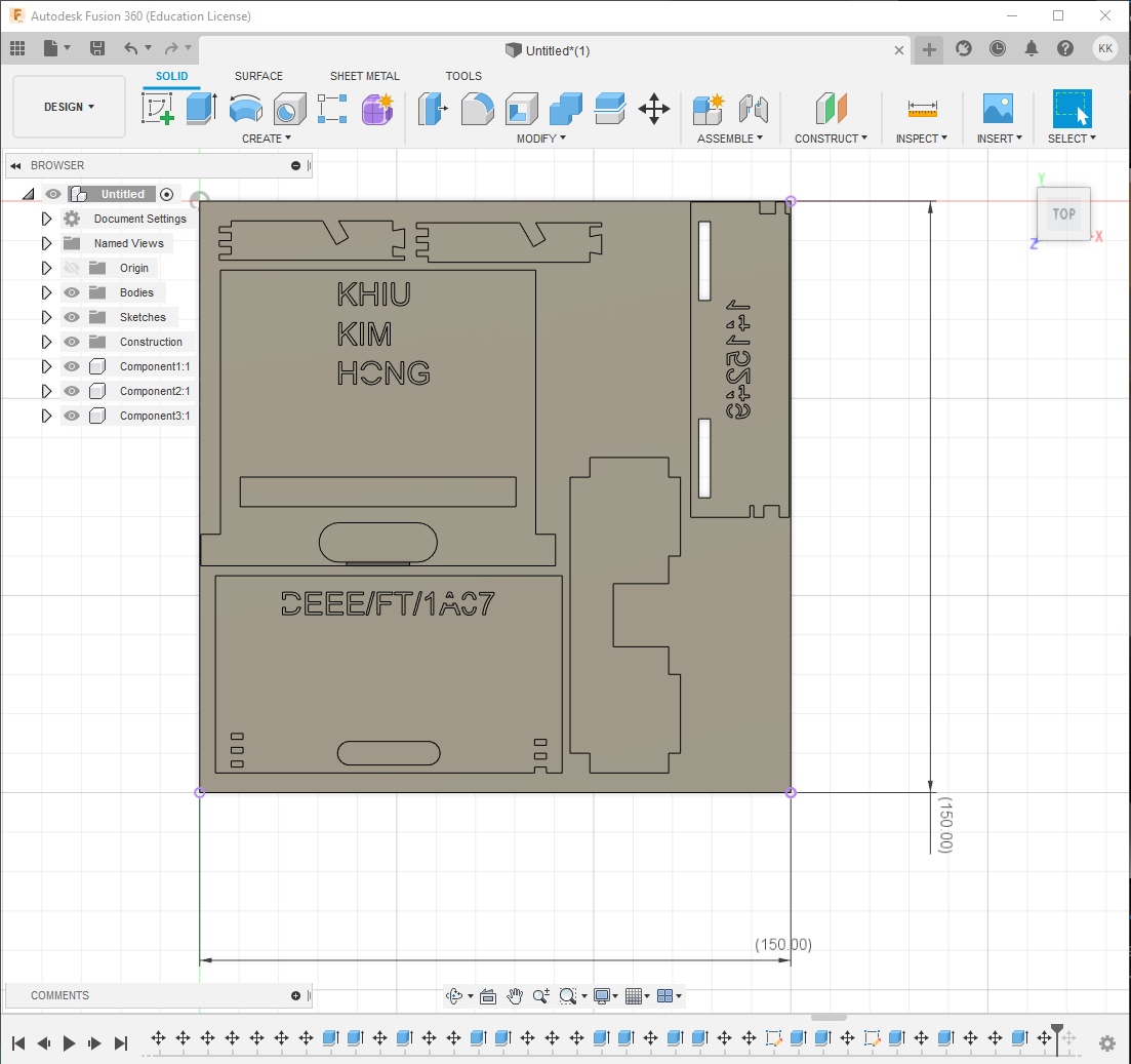 |
Next, a new base of 150mm by 150mm by 3mm was drawn and extruded.
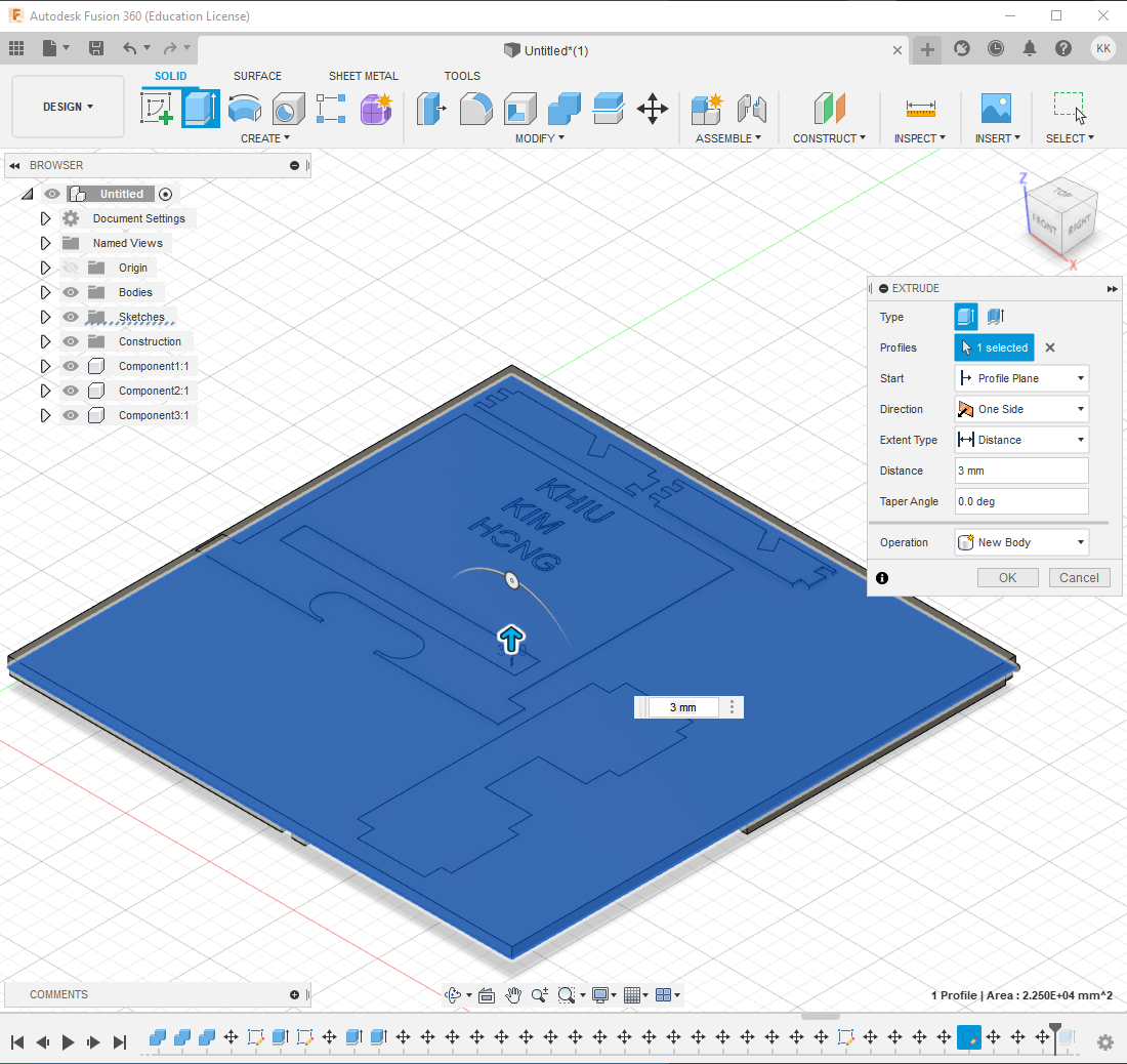 |
Lastly, the combine:cut command was used to ‘cut’ the new base.
|
Both files were then exported and submitted accordingly.